Recently, I came across dancesWithMachines’s blog post that attempted to remote control their
Creality Filament Dry Box 2.0 by spoofing the physical rotary encoder responsible for controlling
the dryer. However, this method had some limitations; for one, it relies on mimicking real input, as
if a person would have physically turned the dial. This becomes an issue if someone were to accidentally turn
the knob, breaking the assumed state of the dryer. This also does not allow for pulling any sort of data
from the box, such as the remaining runtime, temperature, and humidity, which would be great to display
within OctoPrint and Home Assistant for remote monitoring.
The original author decided to pursue this method because of the simplicity, as it requires much less
reverse-engineering of the hardware & firmware, and doesn’t involve debugging the microcontroller, which
I would normally completely agree with:
The idea of controlling the dryer via UART really stuck with me, but I didn’t feel like reverse-engineering
a $36 device (as of today, there’s a sale on Creality’s website) that’s essentially just a hair dryer in a box.
However, I was interested in dipping my toes into hardware reverse-engineering anyways, and decided to have a crack at it.
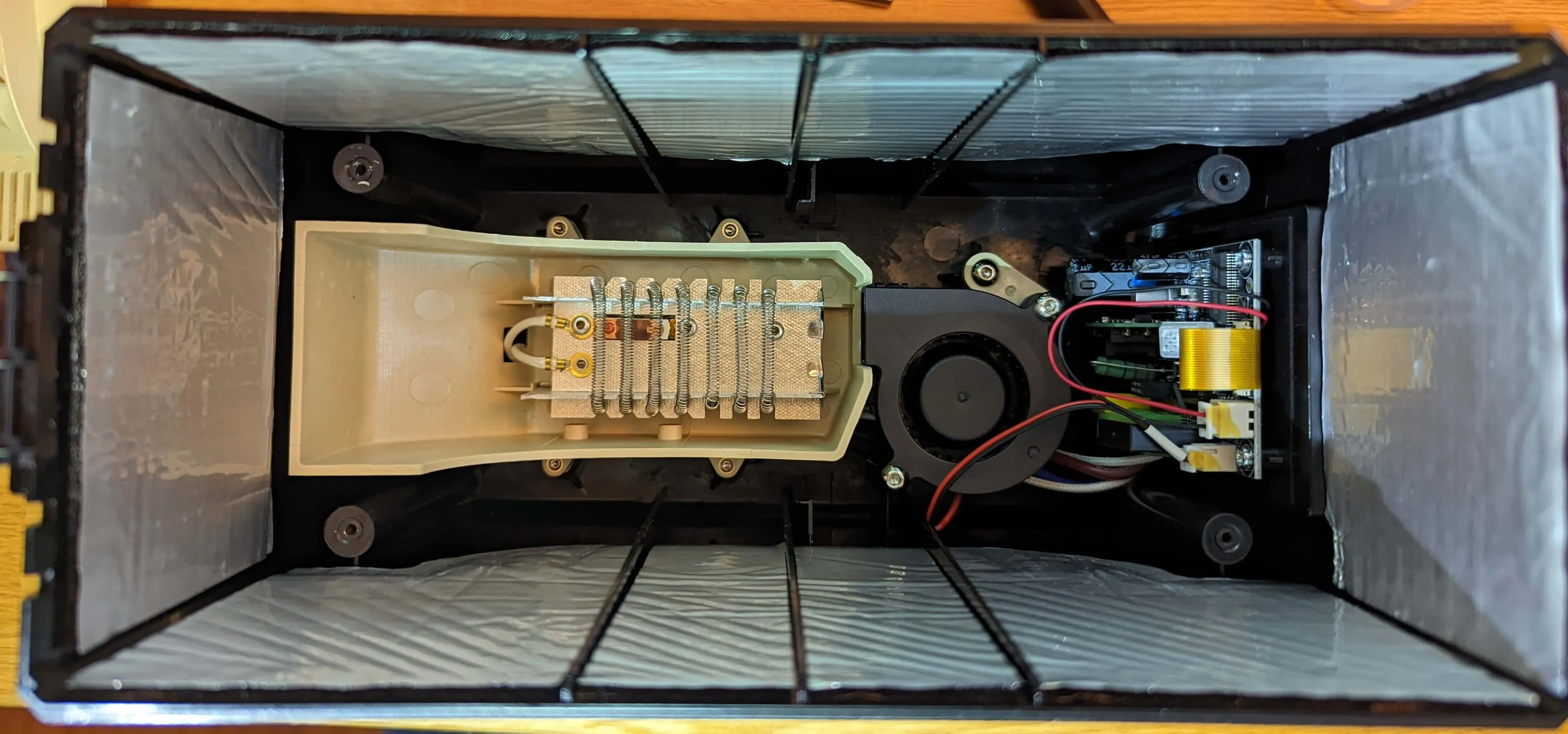
After removing 4 screws holding the inner metal cover in place, all of the electronics can be exposed:
The entire device is quite simple, composed of insulated heating coils, a small fan, and a unified
microcontroller/power supply board that powers everything and controls the entire dryer.
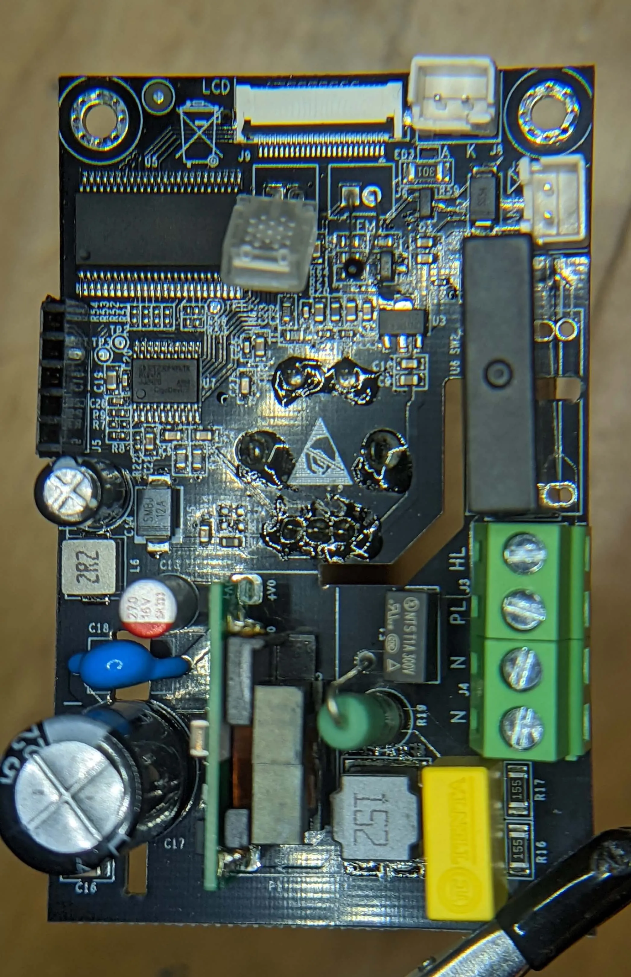
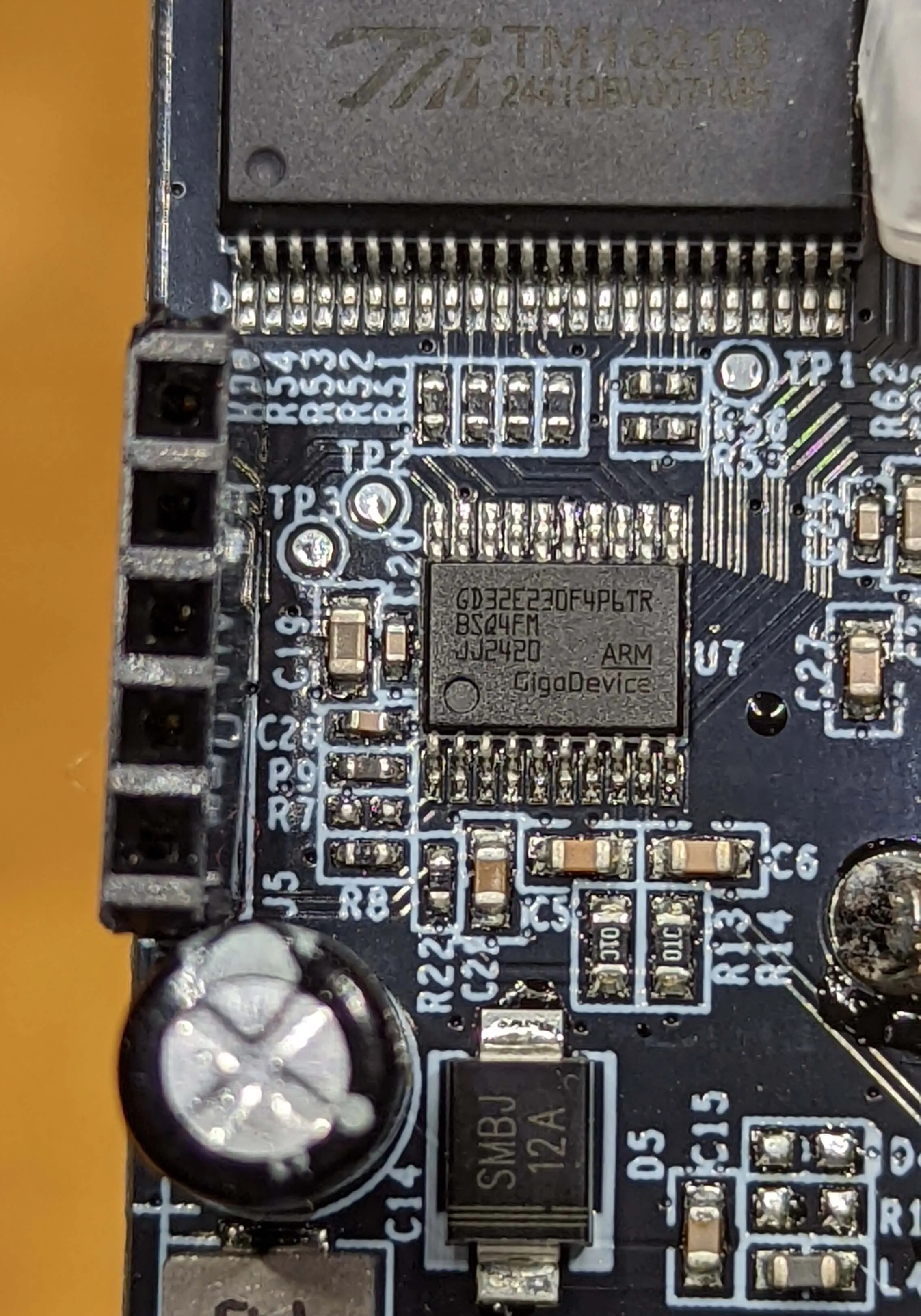
After carefully removing the main board, I was able to identify an unpopulated 5-pin header (I took the photographs
below after I had already soldered my own header) right next to a GD32E230F4P6TR microcontroller, which is part
of the gd32e23x / gd32e230 series of ARM Cortex-M23 MCUs.
The specific variant present on this board has the following features:
TSSOP20 form factor
Max clock speed of 72MHz
16K of flash memory onboard
4K of SRAM
Serial Wire Debug (SWD) & UART
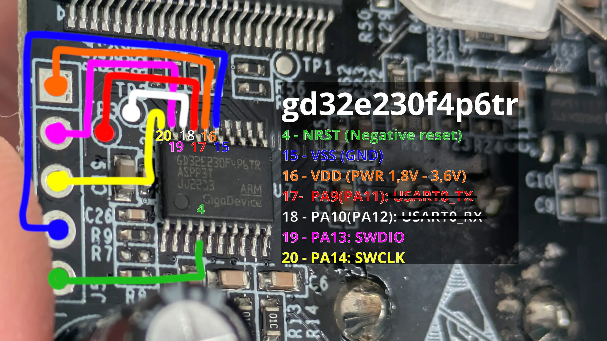
Thankfully, the original blog post has already identified each debugging header pin (ignore the UART test points):
As it turns out, this is a Serial Wire Debug (SWD) port, a proprietary debugging protocol for ARM chips, similar to JTAG
but with only 2 signal lines. While this board does seem to have broken out the UART TX/RX pins into test points,
the original blog post mentioned that they were not able to make the MCU respond.
Thankfully, debugging microcontrollers through JTAG and SWD is quite easy if you have access to another microcontroller
with GPIO, such as a Raspberry Pi! No expensive external JTAG/FTDI converters are necessary.
I grabbed a Raspberry Pi 3B+ that I had laying around, although any* Raspberry Pi should work for this task.
As for debugging software, I opted to use OpenOCD (Open On-Chip Debugger), which has great support for
connecting to a wide array of MCUs, over a large variety of “adapters”. OpenOCD, unlike pyOCD, has support
for using the RPi’s GPIO pins to control SWD/JTAG, making it especially suitable for this task. Additionally,
it has explicit support for the gd32e23x series of Cortex-M23 processors.
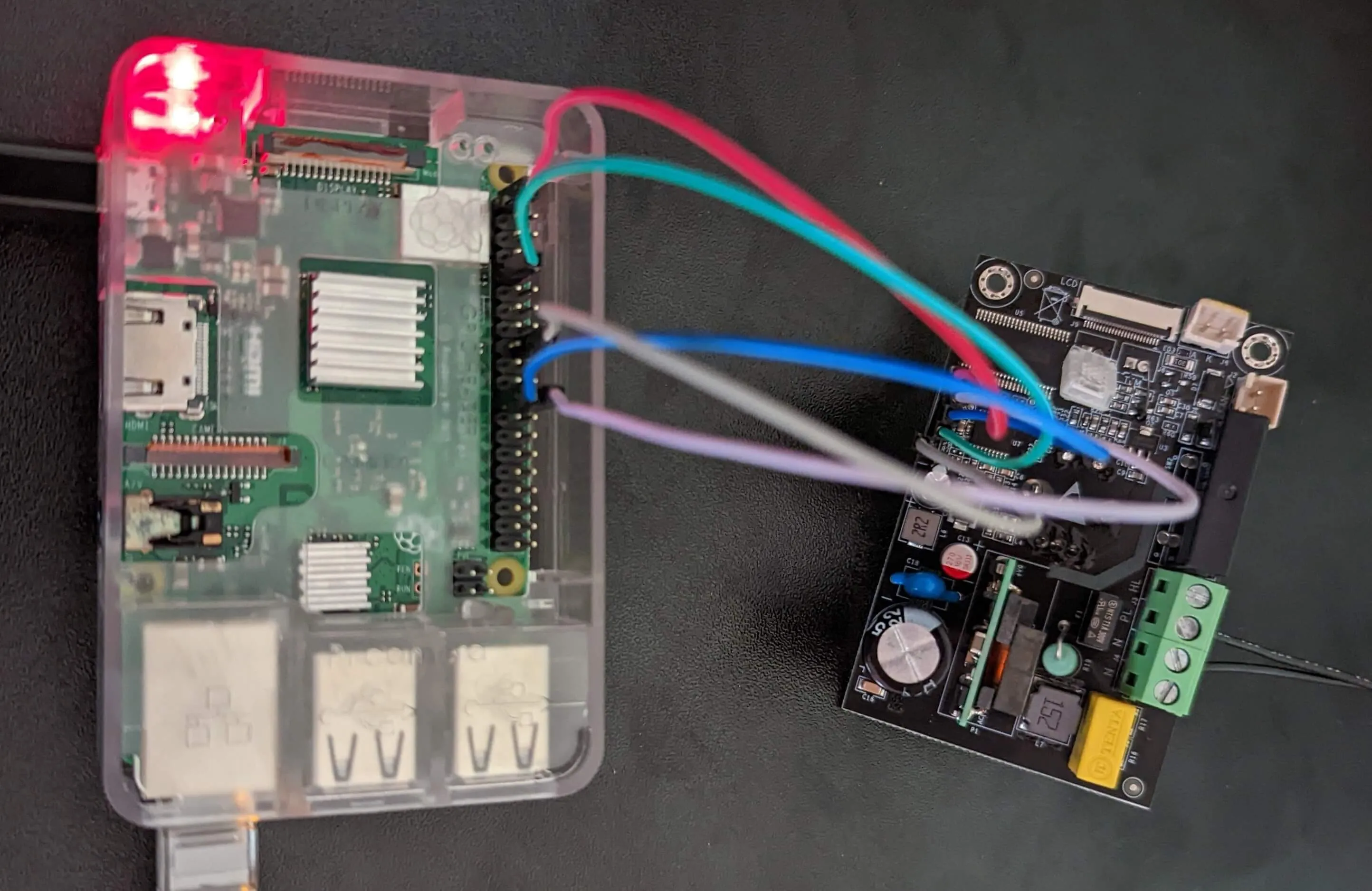
After soldering a few pin headers to the unpopulated pins on the board, I hooked it up to my RPi as follows:
VDD -> RPi v3.3
SWDIO (PA13) -> RPi GPIO8
SWCLK (PA14) -> RPi GPIO11 (CLK)
VSS -> RPi GND
NRST -> RPi GPIO24
NOTE
The correct wiring & configuration to use with OpenOCD varies between RPi models. Refer to the
available tcl/interface/raspberry*.cfg OpenOCD configuration files for more information.
While the board typically provides power to the microcontroller through the onboard power supply, for
the purposes of testing the SWD connection, this isn’t necessary for now (but the external peripherals
will not work, and the MCU will crash upon being un-halted).
Open On-Chip Debugger 0.12.0+dev-gcd48734 (2026-03-17-02:38)
Licensed under GNU GPL v2
For bug reports, read
http://openocd.org/doc/doxygen/bugs.html
Warn : TMS/SWDIO moved to GPIO 8 (pin 24). Check the wiring please!
srst_only separate srst_nogate srst_open_drain connect_assert_srst
Info : Listening on port 6666 for tcl connections
Info : Listening on port 4444 for telnet connections
Info : BCM2835 GPIO JTAG/SWD bitbang driver
Info : clock speed 1000 kHz
Info : SWD DPIDR 0x0bf11477 DPv1
Error: [gd32e23x.cpu] Cortex-M CPUID: 0x0 is unrecognized
Error: [gd32e23x.cpu] Examination failed
Warn : target gd32e23x.cpu examination failed
Info : [gd32e23x.cpu] starting gdb server on 3333
Info : Listening on port 3333 for gdb connections
Info : accepting 'telnet' connection on tcp/4444
NOTE
The bcm2835gpio adapter that is used by interface/raspberrypi-native.cfg uses specific hardware PWM features
available only on specific GPIO pins to make SWD work. If that isn’t feasible, there is a sysfsgpio adapter
(interface/sysfsgpio-raspberrypi.cfg) that uses a (now-deprecated) kernel API to bitbang the SWD interface
at slower speeds. While I wasn’t able to get it working, YMMW. You may need to re-compile Raspberry Pi’s
OpenOCD fork with ./configure --enable-ftdi --enable-sysfsgpio --enable-bcm2835gpio
to enable the necessary adapter.
Unfortunately, probing the MCU seems to always fail after it resets(?), as evident by this log line:
Terminal window
Error: [gd32e23x.cpu] Cortex-M CPUID: 0x0 is unrecognized
TIP
The OpenOCD flag -c 'debug_level 4' can help with debugging weird connection issues!
Tracing some internal OpenOCD code showed that the CPUID, located at address 0xE000ED00, always read as zero.
Assuming that this was the result of the MCU still being under reset by the time OpenOCD attempts to probe it,
I attempted to re-initialize the MCU again:
Terminal window
$ telnet localhost 3333
Trying ::1...
Connection failed: Connection refused
Trying 127.0.0.1...
Connected to localhost.
Escape character is '^]'.
Open On-Chip Debugger
> reset init
[gd32e23x.cpu] Cortex-M23 r1p0 processor detected
[gd32e23x.cpu] target has 4 breakpoints, 2 watchpoints
[gd32e23x.cpu] halted due to debug-request, current mode: Thread
xPSR: 0x01000000 pc: 0x080000e0 msp: 0x20000570
And we’re in!
Unfortunately, this was the point at which I got stuck. I was not able to consistently figure out how
to pull the MCU out of a reset upon connecting, whether it had something to do with improperly wiring
the NRST pin, or an incorrect srst configuration for this chip.
After OpenOCD would correctly detect the MCU as a Cortex-M23 and halt it, manually unhalting afterwards
would briefly spin up the fans, and then the MCU would always reset itself. I presume this is likely some
sort of failed startup/self-test sequence, and I was not able to figure out how to go forwards from here.
IMPORTANT
Before you do anything else to the MCU, make sure to DUMP THE FIRMWARE and save it!
There is NO WRITE PROTECTION, and it’s very easy to accidentally wipe the entire flash
(like I did by mixing up two commands), and brick your dryer without a backup.
From an OpenOCD telnet session:
Terminal window
> dump_image flash.backup.bin 0x08000000 0x4000
dumped 16384 bytes in 0.280870s (56.966 KiB/s)
If anyone is interested in reverse engineering the firmware, I’ve uploaded my
dump!
I attempted to disassemble, but I’m not familiar with how this MCU works at all,
and it ended up being a waste of time.